
On the ONVIF settings tab, the administrator configures camera connection via the ONVIF protocol.
Setup includes:
-
Camera connection scheme.
-
Camera connection mode.
-
Input of required parameters according to the selected combination of the scheme and mode.
Once the ONVIF-comliant camera is connected, the administrator can set up Services:
-
PTZ. This option is available for cameras equipped with remote pan, tilt, and zoom (PTZ) functionality.
-
Events retrieval.
Before beginning configuration, ensure that an ONVIF user profile has been created and configured within the camera's web interface.
Camera connection scheme
The ONVIF camera connection scheme is selected based on the network architecture, specifically:
-
NAT presence: depends on whether a NAT-enabled device is positioned upstream of the IP camera. Such a device translates the camera's private IP address (inaccessible to platform) into an external static IP address that is reachable by the platform.
-
Network type: depends on the network environment used for data and video transmission between the IP camera and the platform components – whether traffic remains within a closed local network without Internet access or routes through an Internet-enabled environment.
Under Camera connection scheme, select a relevant option:
-
Internal network. This scheme is designed for environments where video and data transmission between the IP camera and platform components occurs within a closed local network without Internet access, where no upstream NAT devices are present. While the camera and platform components may reside on different networks, cross-network routing must be configured. The local network must utilize static IP assignments exclusively, as DHCP is strictly prohibited in this configuration.
-
Internal network (NAT Intranet). This scheme is designed for environments where video and data transmission between the IP camera and platform components occurs within a closed local network without Internet access, but a NAT-enabled device is positioned upstream of the IP camera. This NAT device translates the camera's private IP address (inaccessible to platform components) into a “gray” static IP address belonging to the NAT device, which is reachable by the platform.
-
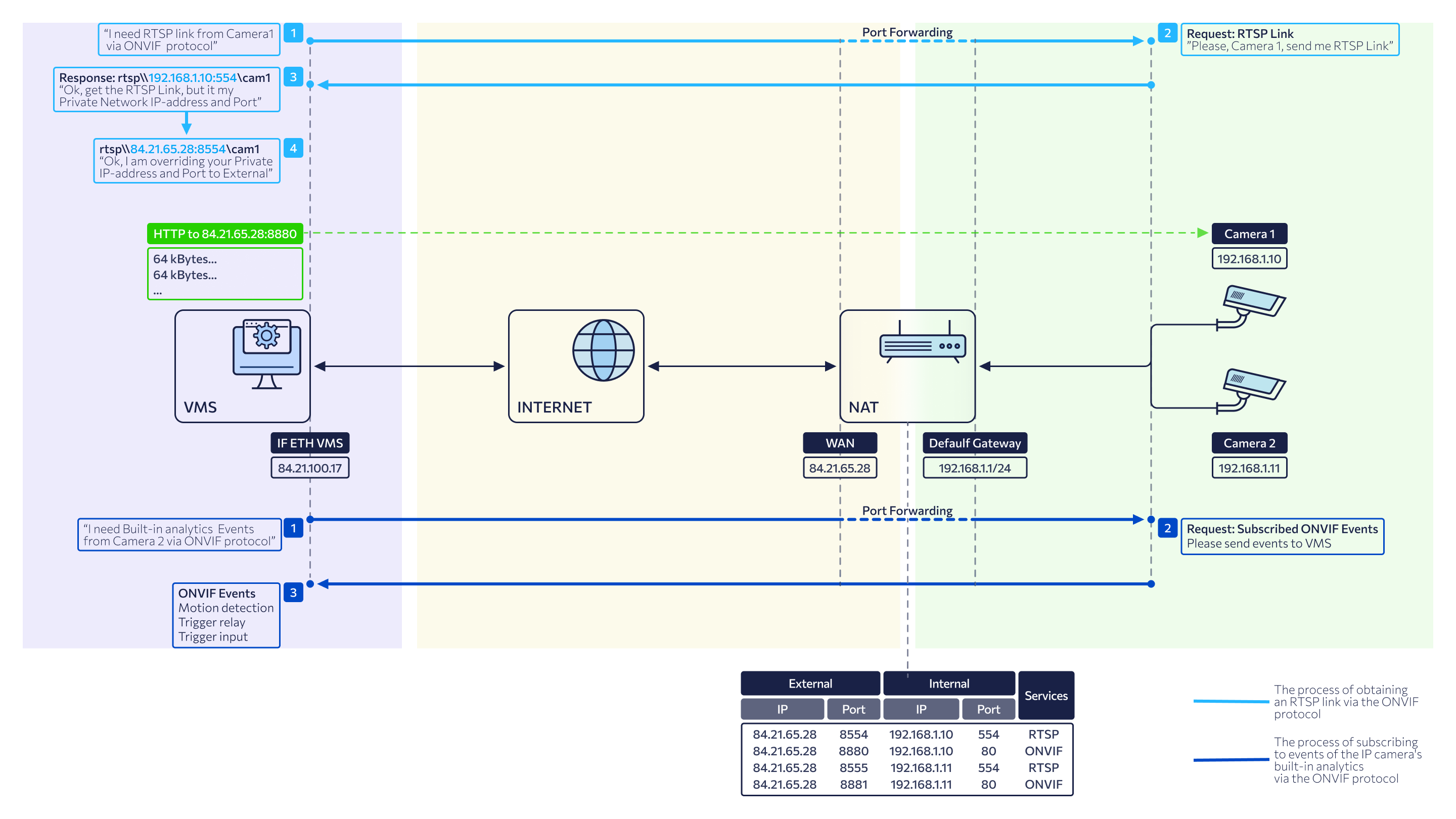
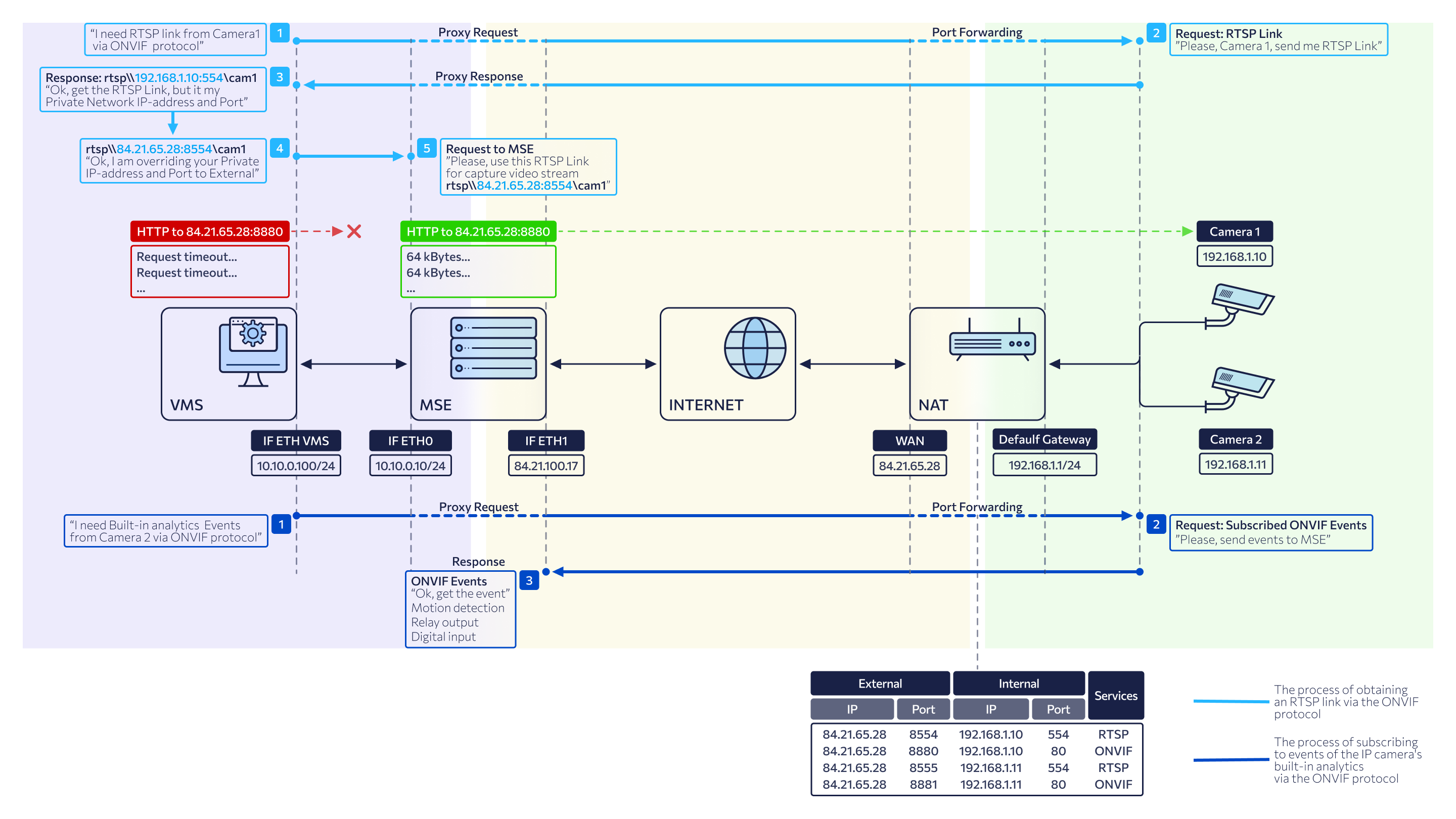
External network (NAT Internet). Select this option if the camera is located on a remote network accessed via the Internet. In this configuration, a NAT-enabled device is positioned upstream of the IP camera to translate its private IP address (inaccessible to platform) into a “white” static IP address on the NAT device.
Depending on the selected connection scheme, the VMS controller processes network parameters received from the camera via ONVIF as follows:
-
When Internal network is selected, the IP Overriding function is disabled. The VMS controller uses the original (internal) IP address and port returned by the camera without any modifications. This mode is designed for operation strictly within a local area network (LAN).
-
When Internal network (NAT Intranet) or External network (NAT Internet) is selected, the IP Overriding function is enabled. The VMS controller intercepts the internal IP address and port provided by the camera in its ONVIF response. It then replaces these values with the WAN IP address and WAN RTSP port manually configured by the administrator in the connection settings. These overridden values are then applied to the RTSP stream links displayed on the Video Streams tab.
Camera connection mode
The connection mode defines the data transmission logic between the camera and the platform:
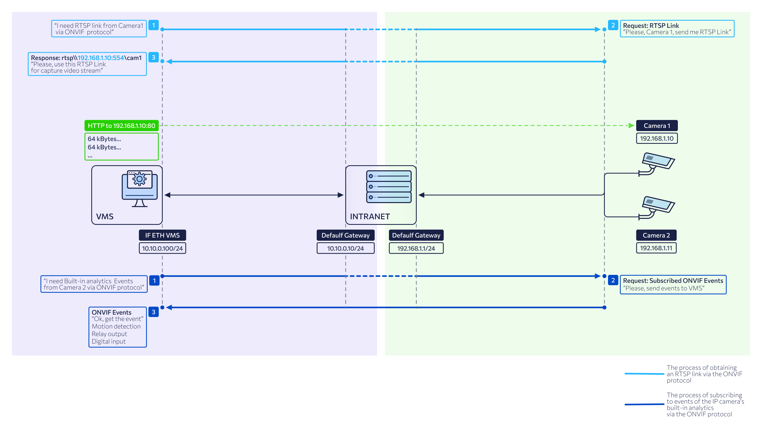
Direct: the camera and the VMS controller exchange data directly, without intermediate servers. All traffic – including control commands, ONVIF events, and video streams – are transmitted straight from the camera to the VMS controller. To subscribe to ONVIF events, the system uses the network address of the host server where the VMS controller is running.
Proxy: interaction between the camera and the VMS controller is routed through a mediaserver. The mediaserver receives video streams and ONVIF events from the camera and forwards them to the VMS controller. The event server address (internal or external IPv4) used for ONVIF subscriptions is selected automatically based on the camera’s specific connection scheme.
Direct mode doesn’t support ONVIF event-based recording.
Camera autoprovisioning
Dynamic Host Configuration Protocol (DHCP) is utilized during automatic camera configuration (auto-provisioning). For cameras connecting to the platform via ONVIF auto-provisioning, Direct mode is enabled by default.
When adding a camera and streams in auto mode:
-
All fields on the ONVIF settings tab are unavailable until the camera receives an IP address (specifically, until the DHCP server callback notification is received).
-
Once an IP address is successfully assigned to the camera and stream creation on the media server is complete, all fields are automatically populated with the camera's current parameters/ Upon successful IP assignment and stream initialization on the mediaserver, the fields are automatically populated with the camera's current parameters but remain read-only.
Manual configuration is unavailable while the camera is actively connected via the ONVIF protocol. To proceed with changes, select Disconnect. Refer to the following section for the disconnection procedure.
.png?cb=d73f1ca3b814ad806f4a0b2eda9fd04e)
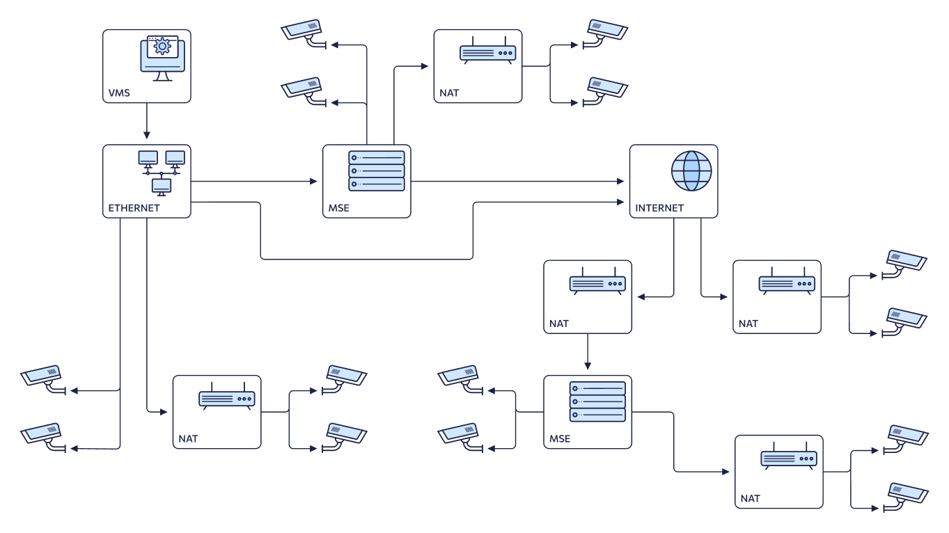
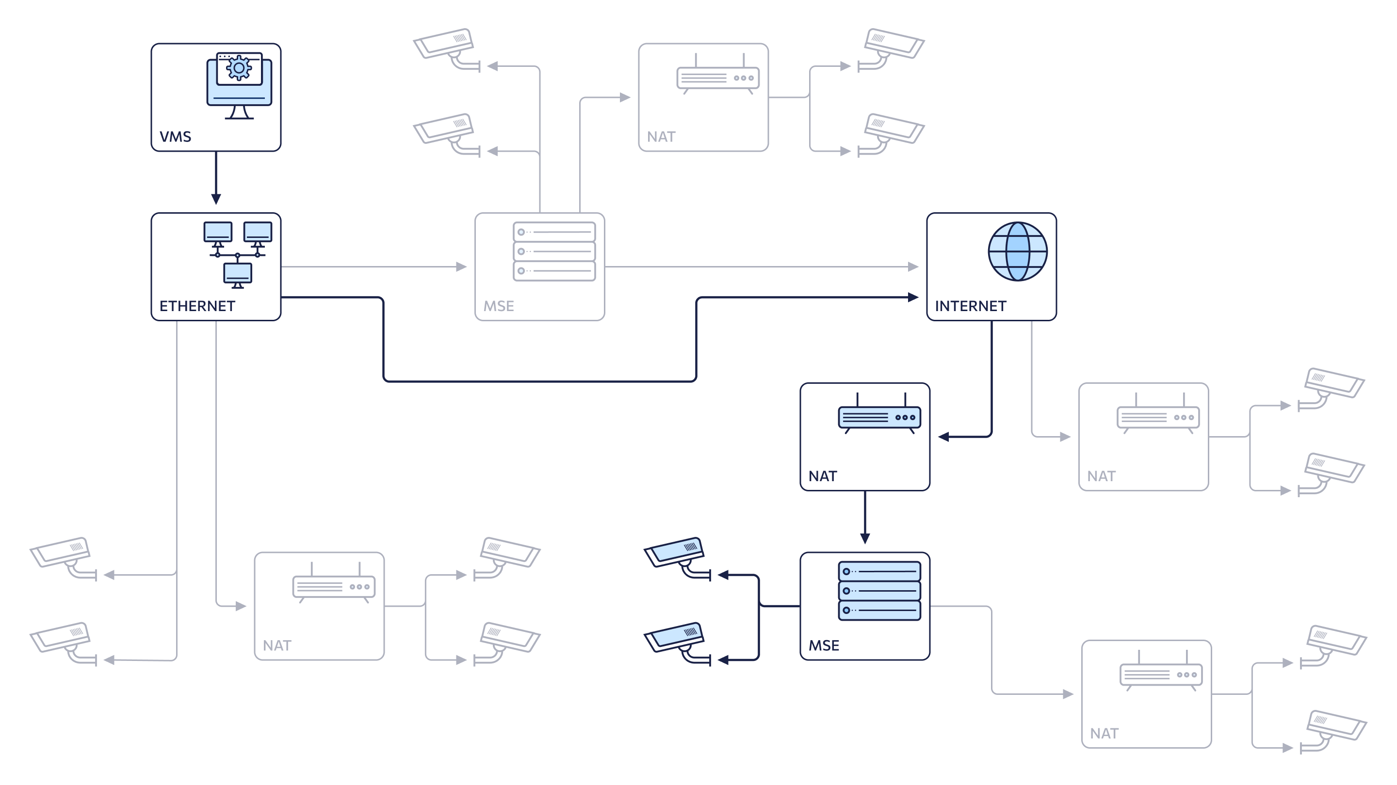
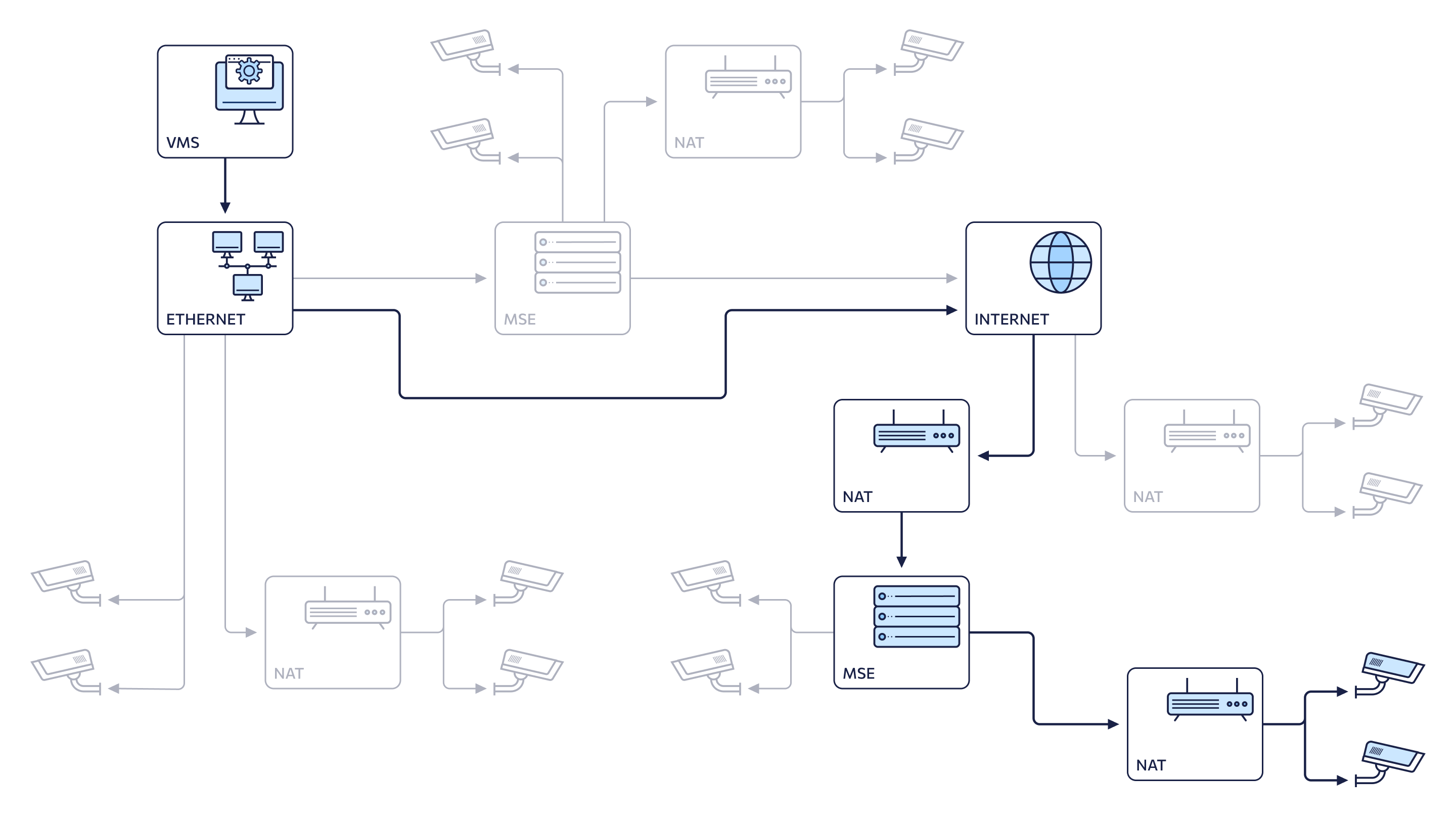
Camera connection configurations
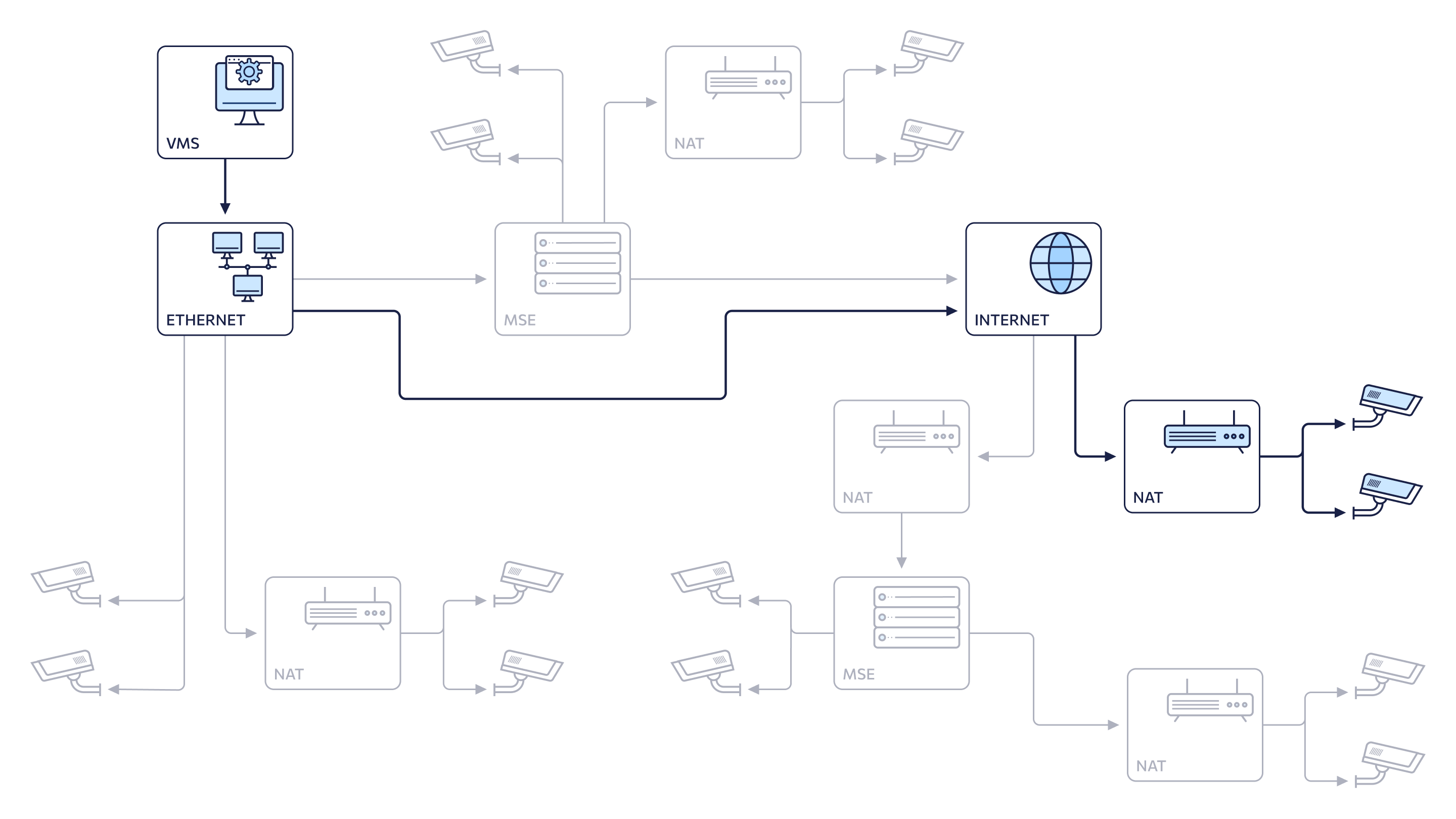
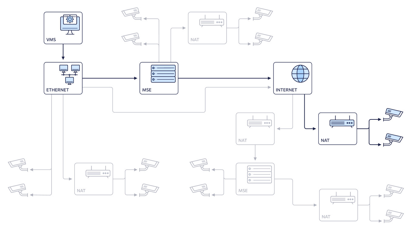
The general connection diagram illustrates various network configuration options: local network with direct camera access, local network with proxying via Media Server (MSE), local network with a camera behind NAT, among others.
Six distinct network configurations are possible based on the chosen combination of connection scheme and data transfer mode. Selection depends on the specific network architecture and whether the camera is accessed directly through the VMS controller or via a media server.
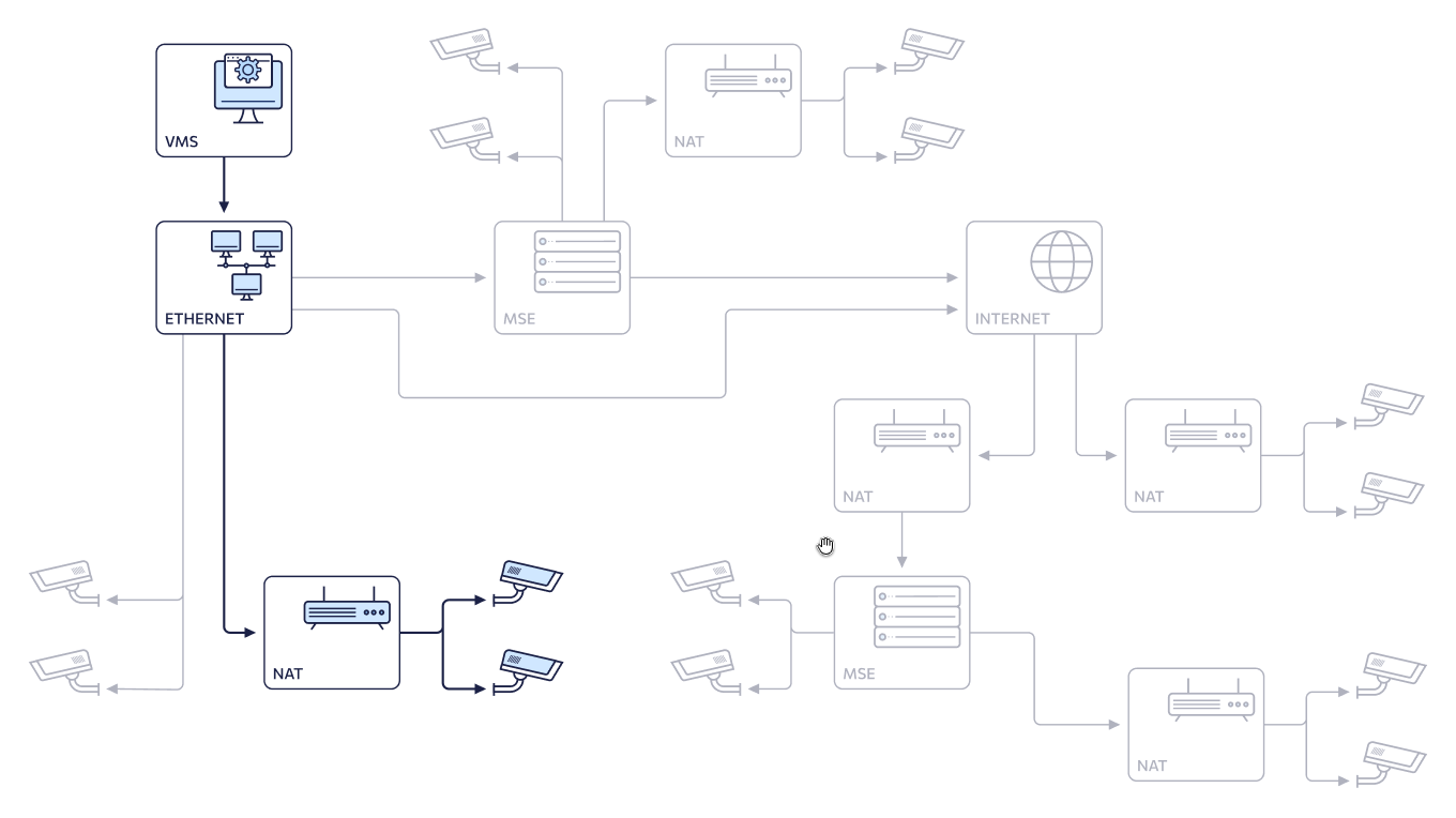
1. Internal network (default)/Direct
The configuration on the general connection scheme:
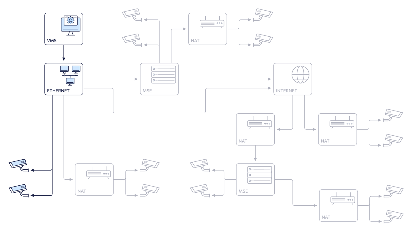
The network configuration:
Under ONVIF connection parameters, the fields defined as follows:
-
IP address: the physical IPv4 address of the camera's network interface.
-
Port ONVIF: the camera port used for communication between the device and platform via the ONVIF protocol. This value depends on the camera's specific ONVIF port. The default value is 80.
-
Port RTSP: the camera port used to establish a connection and configure video transfer between the IP camera and platform components. This value depends on the camera's RTSP port configuration. The default value is 554.
-
Login, Password: the credentials for an ONVIF user account with Administrator rights.
Once the camera is successfully connected:
-
The Video Streams tab automatically populates the RTSP stream paths using the camera’s IP address and port without modification.
-
ONVIF events are routed to the network address of the server where the VMS Controller is deployed.
-
Camera management is handled directly, without utilizing the mediaserver.
-
ONVIF event-based archive recording isn’t supported.
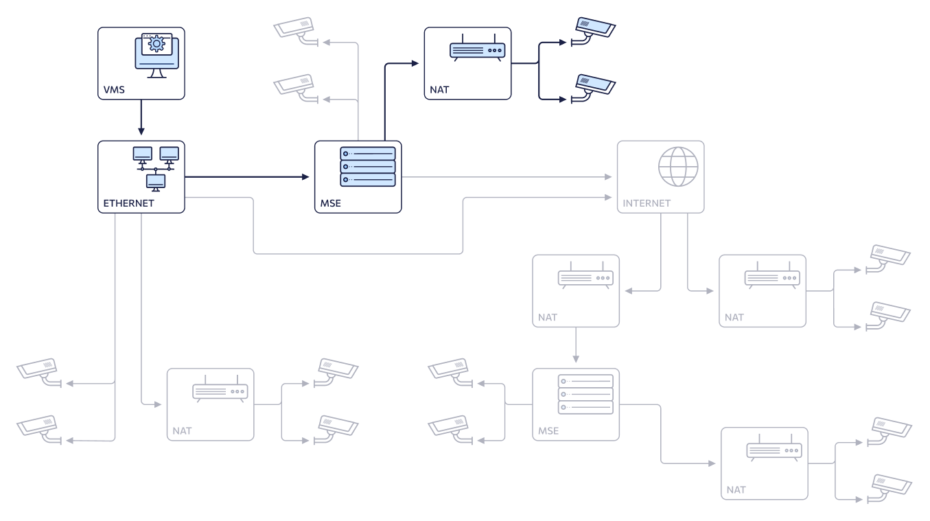
2. Internal network (default)/Proxy
Possible configurations on the general diagram:
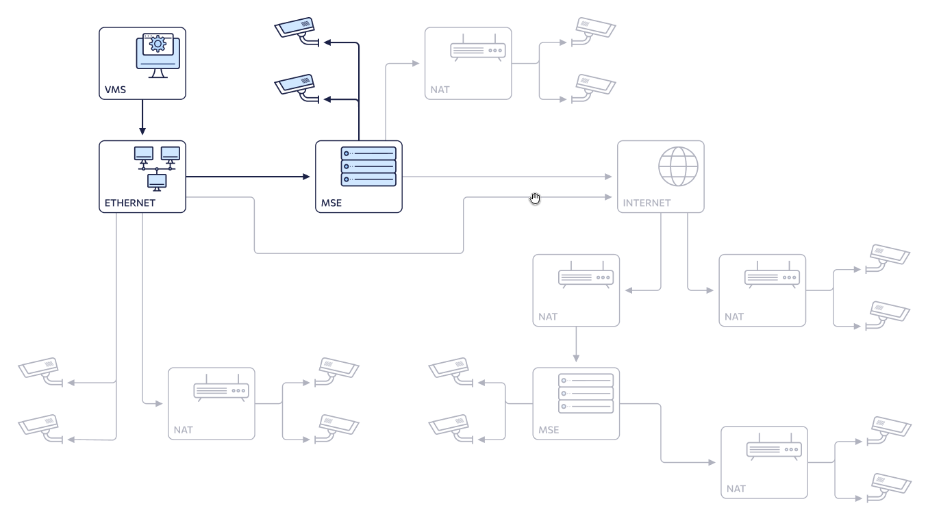
Network configuration:

Selecting Proxy mode enables manual selection of a mediaserver. The Mediaserver to proxy drop-down list populates with all mediaservers accessible to the administrator, encompassing all authorized groups and clusters.
Under ONVIF connection parameters, the fields defined as follows:
-
IP address: the physical IPv4 address of the camera's network interface.
-
Port ONVIF: the camera port used for communication between the device and platform via the ONVIF protocol. This value depends on the camera's specific ONVIF port. The default value is 80.
-
Port RTSP: the camera port used to establish a connection and configure video transfer between the IP camera and platform. This value depends on the camera's RTSP port configuration. The default value is 554.
-
Login, Password: the credentials for an ONVIF user account with Administrator rights.
Once the camera is successfully connected:
-
The Video Streams tab automatically populates the RTSP stream paths using the camera’s IP address and port without modification.
-
The address defined in the selected media server’s profile under Internal IPv4 address of ONVIF event server is used as the destination for receiving ONVIF events. For details on the server profile management, see the View and edit a mediaserver documentation section.
-
Camera management is handled via the selected mediaserver.
-
ONVIF event-based archive recording is supported.
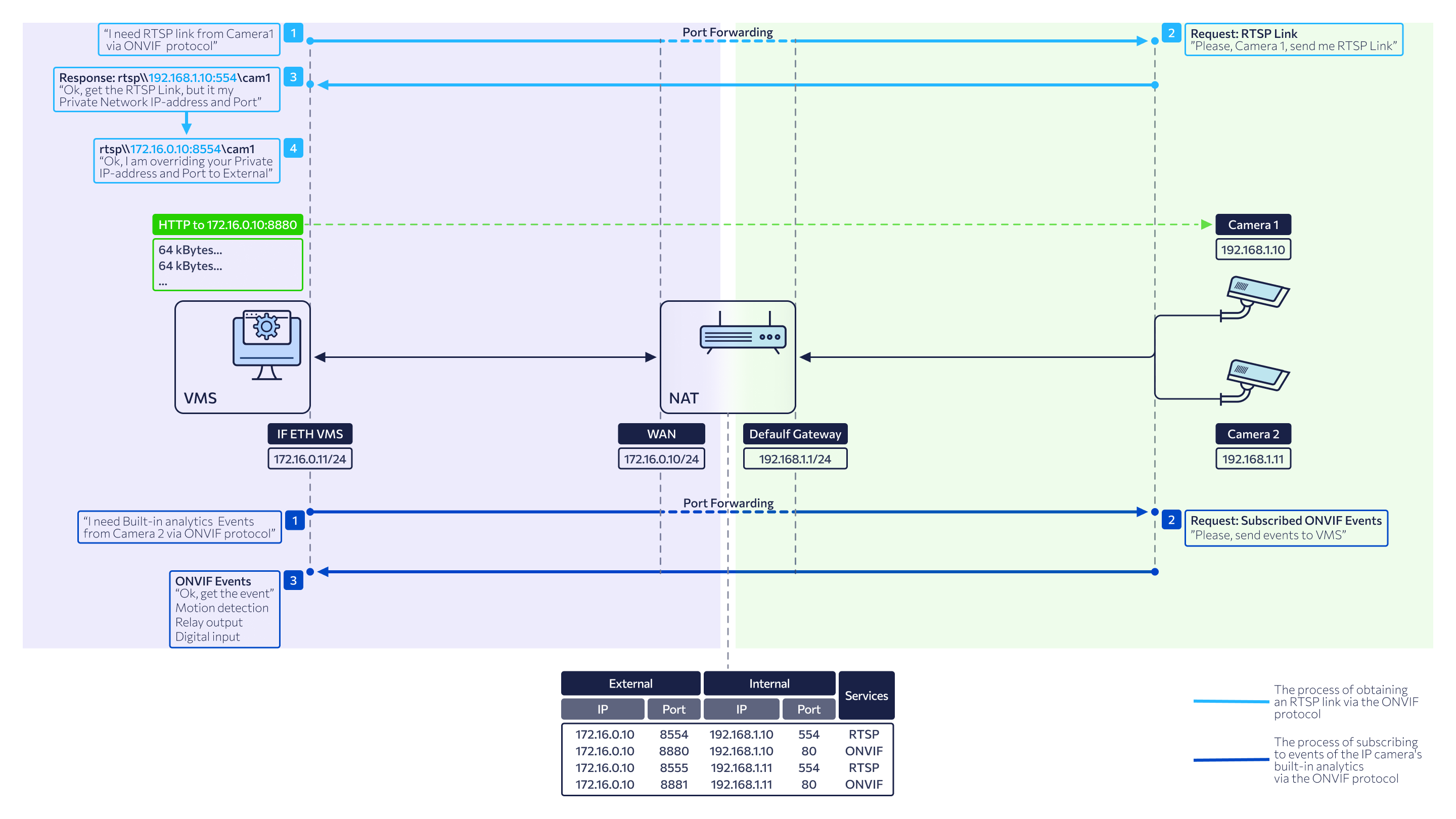
3. Internal network (NAT Intranet) / Direct
The configuration on the general diagram:
The network configuration:
Under ONVIF connection parameters, the fields defined as follows:
-
IP address: is a 'gray' WAN IP address of the router, which has port forwarding configured to provide access to the camera's internal IP address within the local network (Intranet).
-
Port ONVIF: the camera’s WAN ONVIF port, used for communication between the camera and the platform components via the ONVIF protocol. This value depends on the port forwarding rules configured on the router.
-
Port RTSP: the camera’s WAN RTSP port, used to establish a connection and transmit video streams between the camera and platform components. This value is determined by the port forwarding rules configured on the router.
-
Login, Password: the credentials for an ONVIF user account with Administrator rights.
Once the camera is successfully connected:
-
Upon receiving RTSP links from the camera, the VMS controller automatically replaces the internal IP address and RTSP port provided by the camera with the external IP address and RTSP port specified by the administrator in the connection settings.
-
The network address of the server hosting the VMS controller is used as the destination address for receiving ONVIF events.
-
Communication with the camera is performed directly, without the involvement of a media server.
-
Archive recording based on ONVIF events is unavailable.
-
The system performs a uniqueness validation for the 'gray' IP address and the ONVIF port.
4. Internal network (NAT Intranet) / Proxy
The configuration on the general diagram:
The network configuration:
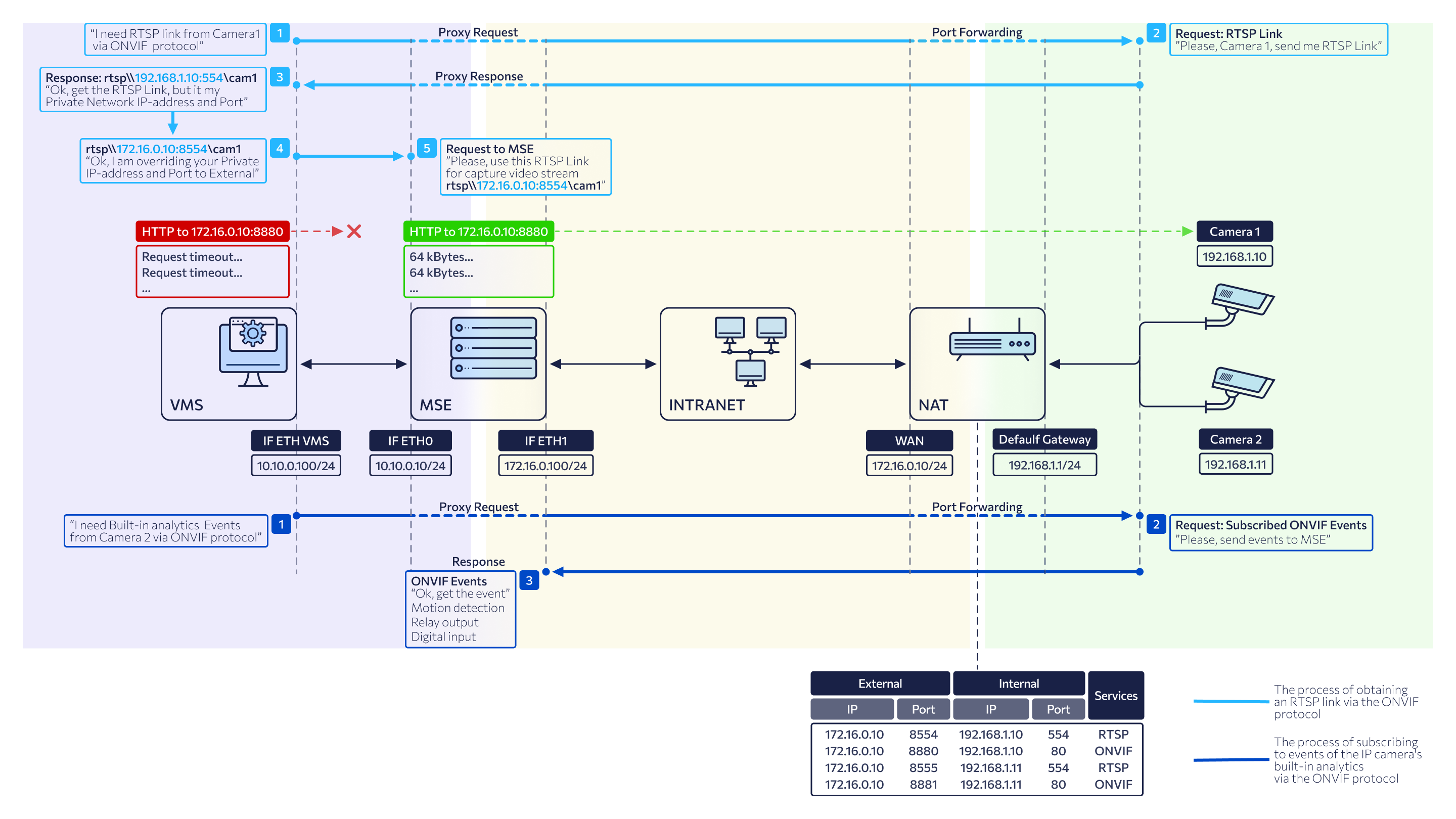
Selecting Proxy mode enables manual selection of a mediaserver. The Mediaserver to proxy drop-down list populates with all mediaservers accessible to the administrator, encompassing all authorized groups and clusters.
Under ONVIF connection parameters, the fields defined as follows:
-
IP address: is a 'gray' WAN IP address of the router, which has port forwarding configured to provide access to the camera's internal IP address within the local network (Intranet).
-
Port ONVIF: the camera’s WAN ONVIF port, used for communication between the camera and the platform components via the ONVIF protocol. This value depends on the port forwarding rules configured on the router.
-
Port RTSP: the camera’s WAN RTSP port, used to establish a connection and transmit video streams between the camera and platform components. This value is determined by the port forwarding rules configured on the router.
-
Login, Password: the credentials for an ONVIF user account with Administrator rights.
Once the camera is successfully connected:
-
Upon receiving RTSP links from the camera, the VMS controller automatically replaces the internal IP address and RTSP port provided by the camera with the external IP address and RTSP port specified by the administrator in the connection settings.
-
The address defined in the selected media server’s profile under Internal IPv4 address of ONVIF event server is used as the destination for receiving ONVIF events. For details on the server profile management, see the View and edit a mediaserver documentation section.
-
Camera management is handled via the selected mediaserver.
-
ONVIF event-based archive recording is supported.
-
The system performs a uniqueness validation for the 'gray' IP address of the router and the ONVIF port.
5. External network (NAT Internet) / Direct
The configuration on the general diagram:
The network configuration:
Under ONVIF connection parameters, the fields defined as follows:
-
IP address: is a 'white' WAN IP address of the router, which has port forwarding configured to provide access to the camera's internal IP address.
-
Port ONVIF: the camera’s WAN ONVIF port, used for communication between the camera and the platform components via the ONVIF protocol. This value depends on the port forwarding rules configured on the router.
-
Port RTSP: the camera’s WAN RTSP port, used to establish a connection and transmit video streams between the camera and platform components. This value is determined by the port forwarding rules configured on the router.
-
Login, Password: the credentials for an ONVIF user account with Administrator rights.
Once the camera is successfully connected:
-
Upon receiving RTSP links from the camera, the VMS controller automatically replaces the internal IP address and RTSP port provided by the camera with the external IP address and RTSP port specified by the administrator in the connection settings.
-
The network address of the server hosting the VMS controller is used as the destination address for receiving ONVIF events.
-
Communication with the camera is performed directly, without the involvement of a media server.
-
Archive recording based on ONVIF events is unavailable.
-
The system performs a uniqueness validation for the 'white' IP address of the router and the ONVIF port.
6. External network (NAT Internet) / Proxy
Possible configurations on the general diagram:
The network configuration:
Selecting Proxy mode enables manual selection of a mediaserver. The Mediaserver to proxy drop-down list populates with all mediaservers accessible to the administrator, encompassing all authorized groups and clusters.
Under ONVIF connection parameters, the fields defined as follows:
-
IP address: is a 'white' WAN IP address of the router, which has port forwarding configured to provide access to the camera's internal IP address.
-
Port ONVIF: the camera’s WAN ONVIF port, used for communication between the camera and the platform components via the ONVIF protocol. This value depends on the port forwarding rules configured on the router.
-
Port RTSP: the camera’s WAN RTSP port, used to establish a connection and transmit video streams between the camera and platform components. This value is determined by the port forwarding rules configured on the router.
-
Login, Password: the credentials for an ONVIF user account with Administrator rights.
Once the camera is successfully connected:
-
Upon receiving RTSP links from the camera, the VMS controller automatically replaces the internal IP address and RTSP port provided by the camera with the external IP address and RTSP port specified by the administrator in the connection settings.
-
The address defined in the selected media server’s profile under Internal IPv4 address of ONVIF event server is used as the destination for receiving ONVIF events. For details on the server profile management, see the View and edit a mediaserver documentation section.
-
Communication with the camera is performed via the selected media server.
-
ONVIF event-based archive recording is supported.
-
The system performs a uniqueness validation for the 'white' IP address of the router and the ONVIF port.
Camera validation and connection
This document section outlines the systematic process triggered when the Connect button is selected.
The system performs a series of validations and configuration steps to ensure seamless integration.
Validation procedures
Form validation:
-
Validation of an IP address format
-
Port range validation: ensures the port is within the valid range of 1–65535.
-
Credentials validation: verifies that the Login and Password fields are populated (Max 100 characters, alphanumeric and special characters allowed).
Camera uniqueness check on the platform:
-
For the Internal network camera connection scheme: checks for an existing camera with the same IP address within the specific network. If a duplicate is found, a notification appears with a clickable link to the existing camera. Selecting this link redirects the administrator directly to the Video Streams tab within the camera profile of the already connected device.
-
For the Internal network (NAT Intranet) / External network (NAT Internet): checks for a unique combination of IP address + ONVIF Port. If a duplicate is found, a notification appears with a clickable link to the existing camera. Selecting this link redirects the administrator directly to the Video Streams tab within the camera profile of the already connected device.
ONVIF availability check: the system sends a request to the camera using the specified address and port to verify support for the ONVIF protocol.
Media server availability check: verifies the connection to the media server. Applicable only when operating in Proxy mode.
Post validation procedures
Once the validation is successfully completed, the system executes the following steps:
-
The retrieved camera information is automatically saved and populated in the interface:
-
On the General data tab of the camera profile: an IP address, device model, manufacturer.
-
On the Provisioning tab in the Network devices list: a network device number (a serial number of the camera), camera MAC address, camera IP address.
-
-
The system establishes a connection using the ONVIF protocol.
-
The connection status updates to Connected
-
The Connect button updates to Disconnect.
-
The system sends an ONVIF request to retrieve RTSP stream links. Any existing manually entered links in the Video Streams tab will be overwritten by the auto-discovered URLs.
-
The received RTSP links are forwarded to the mediaserver to initialize video reception and proxying (this process is handled automatically in Proxy mode).
-
The camera's current configuration is displayed.
-
A list of supported ONVIF services is populated and displayed: PTZ, Event handling.
-
An event – Connection to camera’s ONVIF profile in Direct or Proxy mode – is generated. This log entry is visible within the camera’s profile under the User actions tab.
Set up services
If an added ONVIF camera, among other features, has built-in analytics functions, the VMS administrator can configure the system to receive these analytics events for video system users. All events received from cameras will be automatically available to users in their familiar user interfaces under Events > Camera events. The function of receiving analytics events from ONVIF cameras allows video surveillance system administrators to integrate the built-in analytical capabilities of cameras into the video management system.
Once the ONVIF camera is connected, the administrator can set up Services by selecting relevant checkboxes:
-
PTZ. This option is available for cameras equipped with remote pan, tilt, and zoom (PTZ) functionality. Selecting this service enables an additional camera control panel in the View in player tab.
-
Events retrieval
Before selecting events, ensure these events are set up in the web interface of the camera.
.png?cb=70cd7a694bb1bc37ed11900a090bcb9b)
Events that are available to receive from ONVIF-compliant cameras:
-
Motion detect (ONVIF).
-
Tamper detection. Image too blurry.
-
Tamper detection. Image too dark.
-
Tamper detection. Image too bright.
-
Tamper detection. Global scene change.
-
Event from external system.
-
Event to external system.
-
Configuration changed.
The administrator can track the events that are received from the ONVIF cameras:
-
In the camera profile on the Events tab > the Camera sub-tab.
-
In the Logging section > Events > the Camera events tab.
Configuration change logging: if the ONVIF service settings are modified, the system generates an event: "Modification of camera ONVIF service settings." This record is logged and displayed within the User actions tab of the camera profile.
Stream reconnection
If the system fails to retrieve all or any video stream links during the initial ONVIF profile connection, the administrator will see a notification informing on this. In this case, the Get links to video streams button becomes available to manually re-attempt the discovery process.
Selecting the button triggers a reconnection attempt to the camera's ONVIF profile using the current credentials to retrieve the RTSP links. During this process:
-
Previously assigned video stream UUIDs remain unchanged.
-
All previously recorded archives remain fully accessible and linked to the stream.
If the reconnection attempt fails, an error message is displayed. In this state, the credentials remain editable, and the Connect button is re-enabled for further attempts.
.png?cb=9bf0de3fc82a857223087866547d301c)
Disconnect ONVIF
When the Disconnect button is selected, the system performs the following steps to disconnect from the camera's ONVIF profile:
-
Service termination:
-
Live video streaming to the media server is stopped.
-
Archive recording for the camera’s video streams is terminated.
-
Event unsubscription: the system deletes the active ONVIF event subscription.
-
The video stream link fields on the Video Streams tab are re-enabled for manual editing.
-
Data clearance. The system clears all parameters associated with the previous ONVIF connection, specifically:
-
All data on the Configuration tab is removed.
-
On the ONVIF settings tab, the Login, Password, IP address, ONVIF Port, and RTSP Port fields are cleared.
-
On the ONVIF settings tab, ONVIF event subscription data and enabled ONVIF services are cleared.
-
On the Provisioning tab, the data in the RTSP streams section is cleared.
-
Data update:
-
On the ONVIF settings tab, the Connected status is updated with Disconnected.
-
On the ONVIF settings tab, the Disconnect button is updated with Connect.
Upon successful disconnection from the camera's ONVIF profile, the following requirements are met:
-
On the Video Streams tab, camera video stream UUIDs remain unchanged, even if a different video stream link is inserted. UUIDs are displayed next to the name of the media server to which they belong.
-
The previously recorded camera archive remains accessible.
Additionally, a Disconnection from camera ONVIF profile event is created. The event is displayed:
-
In the camera profile on the User actions tab.
-
In the Logging → Events section on the Cameras tab.